Nikon GPS Adapter V3
Tested working with D200 and D800E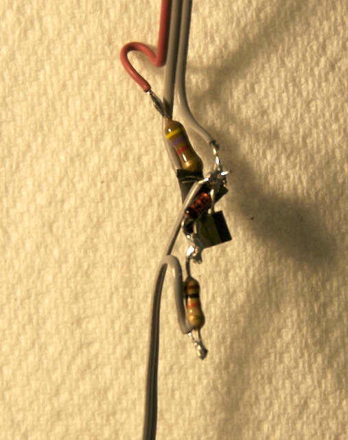
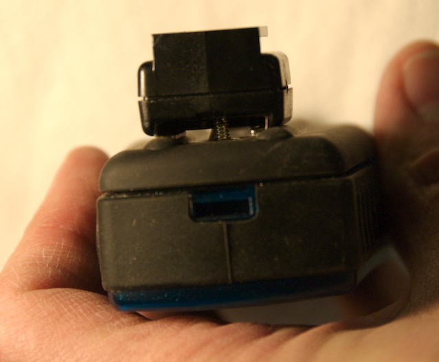
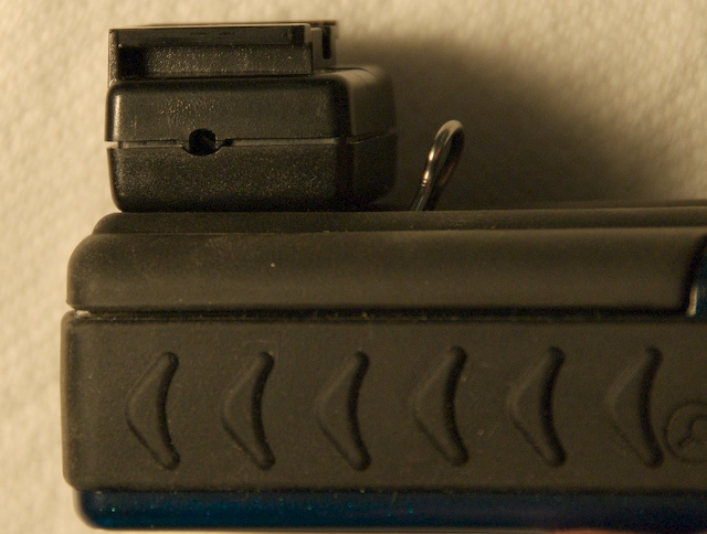
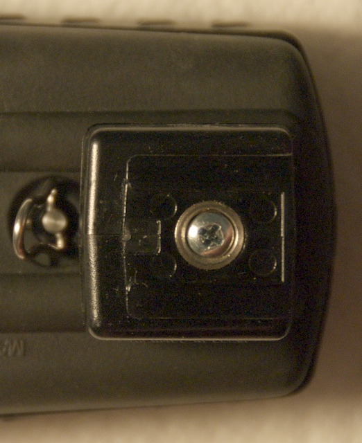
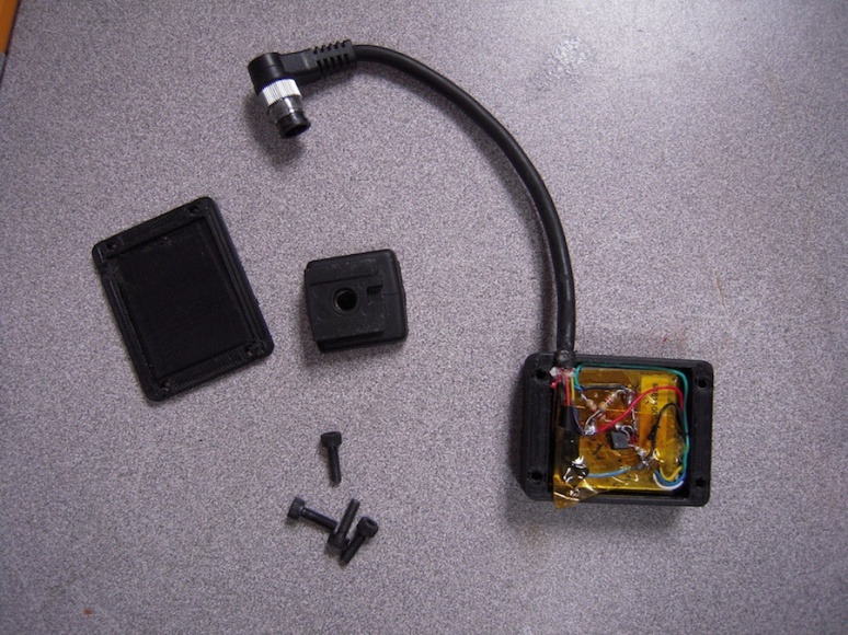
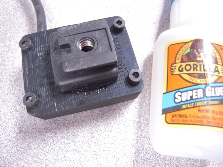
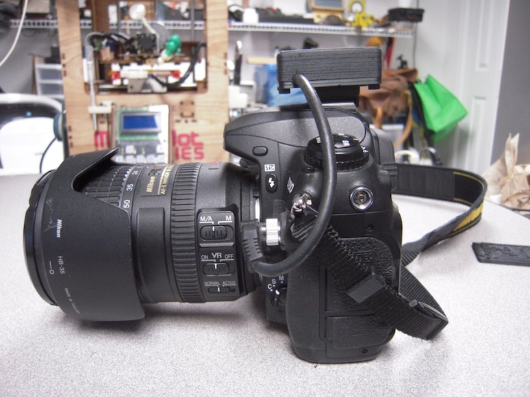
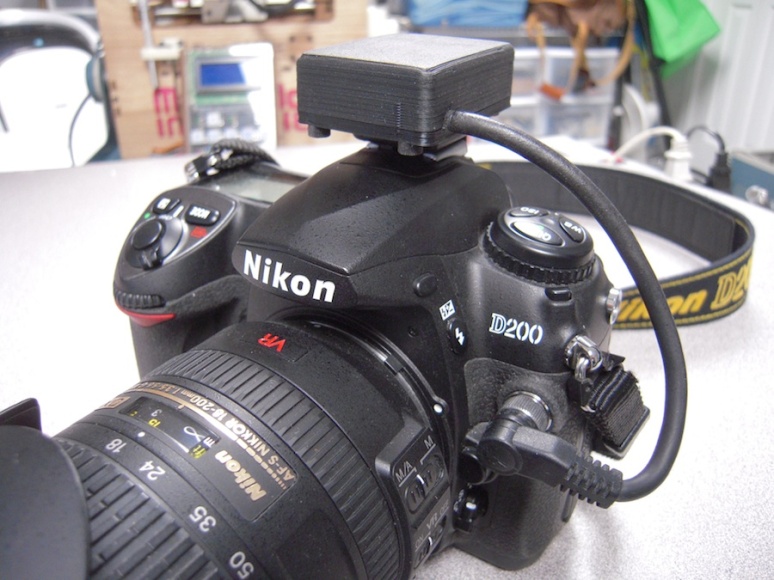
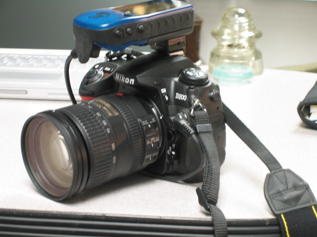
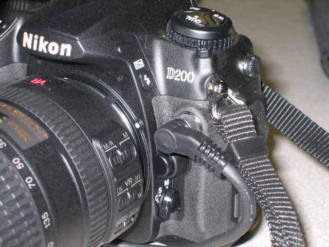
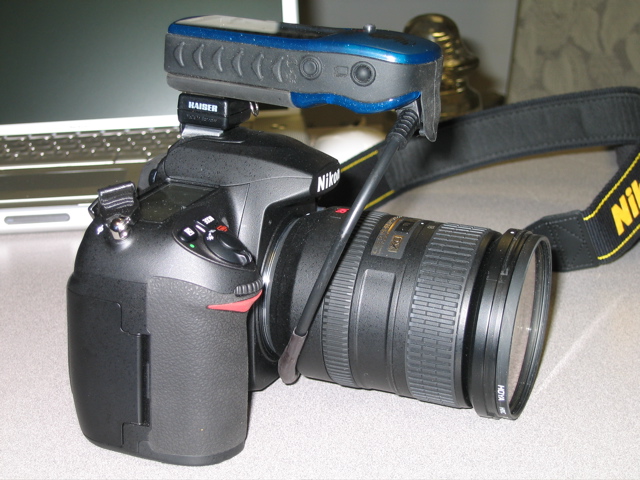
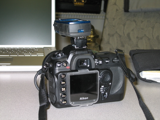
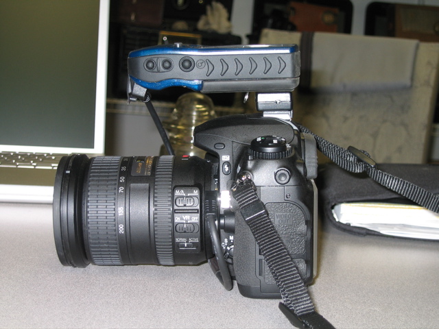
The original version of this uses an external GPS (Garmin eTrex) I’ve just changed it to use a small GPS module from AdaFruit and a custom case created in SolidWorks and printed on my Thing-O-Matic. I’ve kept the original instructions so both versions are covered here.
Note: this needs basic electronic skills, if you don’t feel confident then please don’t attempt it. As it depends upon third party components and cables which may change in orientation and colour coding you should verify all connections and operation before connection to your camera.
I didn’t include an on/off switch in the printed version as I don’t believe it is necessary, I just unplug it when not needed.
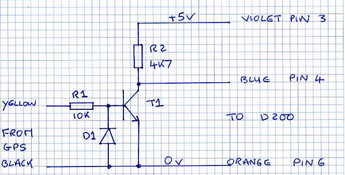
The purpose of this project was to develop a way of installing a GPS on to my D200, mainly as an aid to my landscape photography database rather than for Geocaching etc. After researching on the Internet and judicious use of Google I managed to find the connection details for the 10-pin connector on the front of the D200. Despite extensive searching though I was not able to find out exactly what was contained within the Nikon GPS adapter. From other sites detailing hacks for the GPS adapter it looked like it contained an RS232 to TTL level converter (MAX232 or similar). Now, while it is relatively easy to do it this way it is still pretty bulky and uses several parts. As I was only interested in sending data from the GPS to the D200 then I just had to convert the RS232 level signals from the GPS NMEA 0183 output to the TTL level input of the D200. To achieve this I built a simple inverter using two resistors, general-purpose NPN transistor and a diode. Fig1
Schematic, fig 1
Operation
R1, 10K is used to drive the base of T1 from the RS232 level signals and ensures that T1 is fully turned on when the RS232 signal is high.
D1 protects T1 base-emitter junction from reverse biasing when the RS232 signal goes negative.
R2 is the collector load and is sufficient to pull the input of the D200 high when T1 turns off.
Parts list
R1-10K 0.25W Carbon film resistor
R2-4K7 0.25W Carbon film resistor
D1-1N4148 general purpose Si diode
T1-ZTZ651 or equivalent general purpose Si transistor
Heat shrink tubing
10 pin connector, Nova Photography (http://cgi.ebay.com/Nova-Nikon-MC-35-MC-23-Type-10-Pin-All-Wired-Plug-Cord_W0QQitemZ330072469568QQihZ014QQcategoryZ64345QQssPageNameZWDVWQQrdZ1QQcmdZViewItem)
NOTE: This is no longer listed on eBay and may need some searching to find it. Sometime the shutter release cables advertised have all of the wires in place internally, but YMMV
GPS cable (supplied with GPS or get from eBay)
GPS –I used Garmin eTrex legend from Circuit City but any model with an NMEA output should work
OR
Basic GPS Module PMB-648 https://www.adafruit.com/products/272
There are many of these around and as long as it has a NMEA 0183 output they should work
Flash adaptor-buy from B+H, Adorama or local camera shop
Kapton tape
SuperGlue
TOM- Black ABS
4 x M3x10 bolts
How to do it
Note: This uses basic soldering and mechanical tool skills. If you don’t feel confident then DON’T DO IT! As usual there are no guaranties of any sort with this information, USE AT YOUR OWN RISK.
The flash adaptor
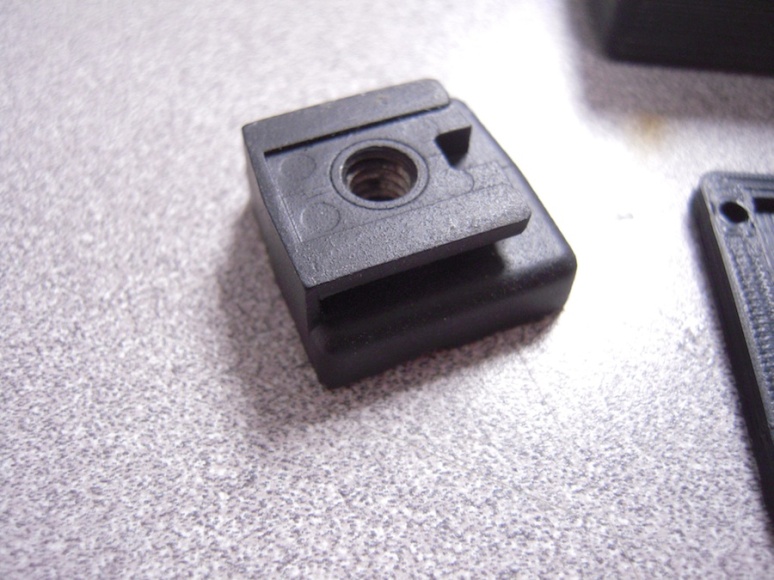
Buy any type of flash adaptor, usually used to give a cord connection for cameras that don’t have an external flash connector.
Drill a clearance hole through the centre of the adaptor for a 4-40 screw (or use M3 if in ROW)
Select a spot on battery cover of eTrex that enables the GPS to sit on top of the camera without projecting into your face when at eye level (see first picture). Mark position and drill and tap a 4-40 (or M3) hole. Use a countersunk screw to fasten the adaptor to the eTrex. The rubber finish to the eTrex ensures a very secure fit. If you’re still concerned then use some adhesive as well. Take care that the screw does not interfere with the flash connections on the top of the camera.
OR
Print the case on your TOM
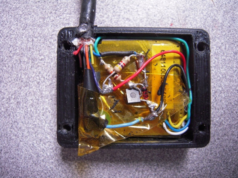
Insert the GPS module, note it’s a tight fit, you may need to trim the cavity to make it a snug fit. Use a dab of hot melt glue to support it if necessary.
GPS Module connections are available at
http://www.parallax.com/Portals/0/Downloads/docs/prod/sens/PMB-648_Specification_V0.1.pdf
Build the circuitry using ‘ugly’ construction (if I was doing this in bulk I’d make a pcb but didn’t feel the need for a ‘one-off’)
Be sure to keep total thickness of circuitry <2mm
Carefully wrap in Kapton, double check for shorts and opens
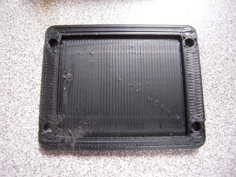
File matching areas in the top and the base to match the cable. I didn’t put this in the model as I wasn’t sure of the fit but very easy to do with a small file
May need to open up the holes in the base
Deliberately left the holes in the top snug so as to make them self tapping for the M3 bolts.
Check all of your connections
Glue the flash adapter to the base of the GPS module. I used superglue which works fine and it’s very secure.
Test
Before connection to the camera, connect a 5V supply and verify that the NEMA RS232 output is driving the transistor and that a 0-5V TTL level output is going to the relevant pin on the D200 connector.
When connected to the D20 the GPS indicator should flash to show that it is receiving data and then go steady when the GPS module has locked on.
Connections
I cut the cables to length so that the cables would fit around and under the lens as the eTrex connector exits to the left (when seen from the front) and the 10-pin connector exist to the right.
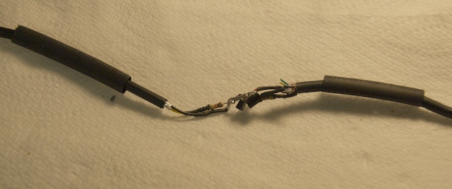
Build the circuit in fig 1 using ‘ugly’ in line construction (see images below) keeping overall diameter small so it fits within heat shrink sleeving. Attach the wires according to fig 1, note, this is the colour code on the connectors I had. Check first using a DMM!!
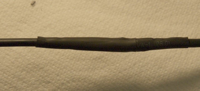
Cover the circuitry with heat shrink sleeving, ensuring that there is no danger of short circuits inside it, I sleeved most of the internal connections with small gauge sleeving as well.
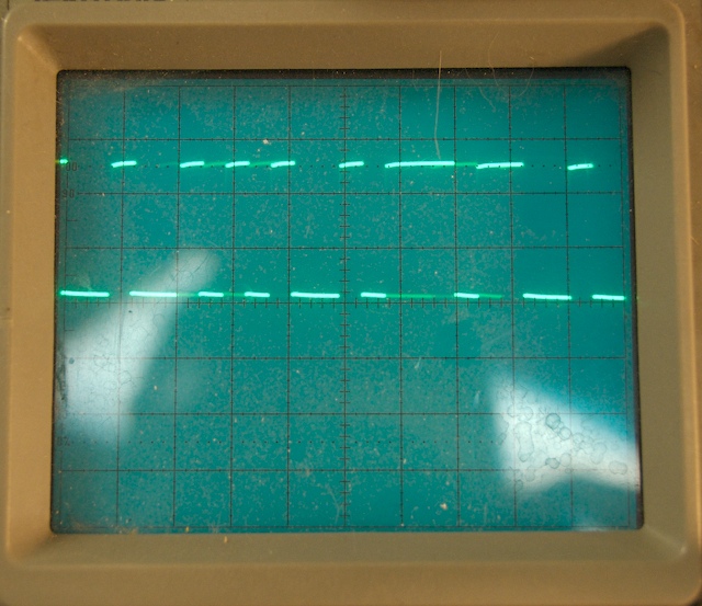
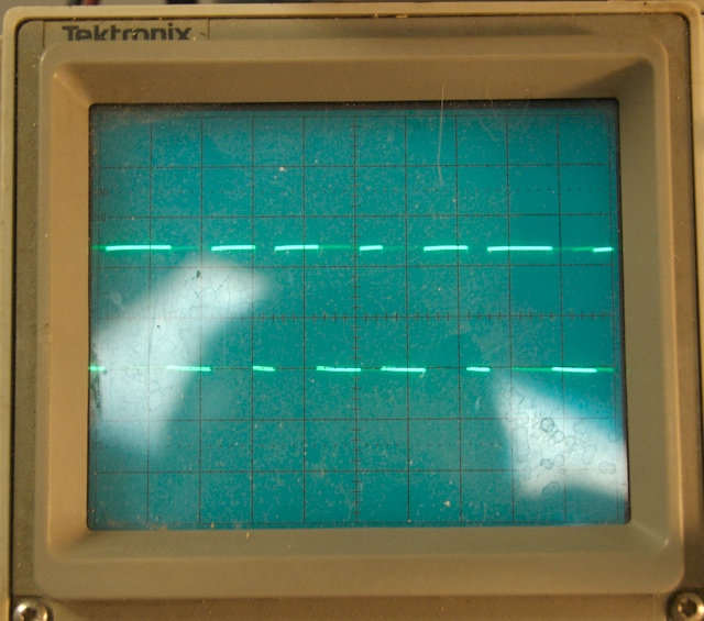
I verified operation with an oscilloscope (see below) but as this is very simple it should not be necessary. Plug into D200, turn on GPS, ensure that NMEA output is enabled and the GPS indicator on the camera should start to flash. As soon as the GPS achieves lock then it becomes a steady indication.
Voila! Enjoy!
Acknowledgements
http://www.hackaday.com/2006/08/21/nikon-d200-gps-adapter/
http://www.k-i-s.net/article.php?article=20
http://www.garmin.com/products/etrexLegend/
http://www.schneordesign.com/Avi/F100/diy_01.htm
http://www.perfect4me.com/Products/mynikon/default.asp
Images
Assembled device before heat shrink
After heat shrink applied
RS232 input (note +/- 3V)
TTL input to D200 (note 0 to 5V)
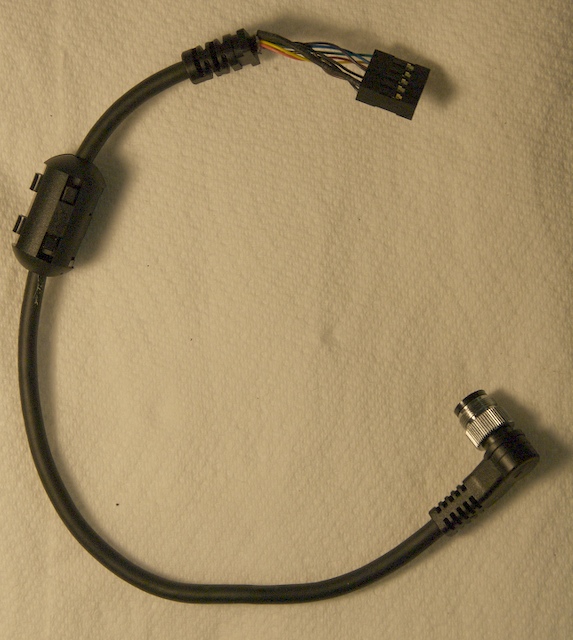
D200 cable, as supplied
Flash adapter on GPS, bottom view
Flash adapter on GPS, side view
Flash adapter on GPS, end view
Bottom view of GPS module in case with level convertor and kapton tape insulation
Case bottom with gap for cable
Hot shoe mounted to case with SuperGlue
Another view of adapter mounted on camera
International SIM Card
Just received my HolidayPhone sim card for iPhone 5 for next trip to UK. Looks to be a really good service, I’ll post more on my return.
Particularly looking forward to getting unlimited Internet access!
http://www.holidayphone.com
Bob
Art and Technology Show at the local RadioShack
Hi,
I had an ‘Art and Technology’ show today at the local RadioShack in Massachusetts which went pretty well. I had my table-top Polargraph running printing pictures of Neil Armstrong, Muhammad Ali, Abe Lincoln etc together with my Thing-o-Matic plus my usual other art stuff!
Also built a simple two axis accelerometer hands on toy for the kids using a servo and a G35 xmas light string. rotating cw/acw moved the lights from centre (Green) and progressively moved towards red the further you went and the servo showed inclination up/down.
Main idea was to show how you can use the Arduinos and Motorshield etc that RS sells and make neat things and
then link it to art,
Think I sparked an interest and the guys at RadioShack thought it neat.
IOZETA Cloud bckup
Hi, I’ve recently changed to OZETA for my cloud backup needs and must admit I find it works very well. I have it on all of my systems and easy for me to access from any platform as well as on my iOS devices.
If your interested check it out at this link
Bob
DrawBot Update
I’m pretty active with the local art association and demo’d my full size DrawBot to them last week. As oart of that we thought it would be useful to develop a smaller machine that could be easily placed on a desktop for use as a demo at art shows and as a crowd puller.
So, serendipitously we had a new PVC fence installed recently and I snaffled some of the offcuts as I thought they would come in useful. Basically I made a large T section from the 125mm square upright pieces and added a plywood board for the paper. Then I installed the Arduino and steppers in the top piece of the ‘T’, finally I added some green and red led’s across the motor drives to add some more ‘pizzazz’.
To add some tilt to it I epoxied two railroad spikes to the bottom (from my metal sculpture work)
Dimensions are 580 x 320 with an effective drawing area of 320 x320
I think this worked out really well and all I need to do know is to tidy it up with some covers!
What do you think?
Homing code for Drawbot
I’ve uploaded the Arduino code for the modified server with the homing routine included.
Let me know if it helps anyone!
Some more images from the Drawbot
Thought I’d post a few more images from the Drawbot
DrawBot
This slideshow requires JavaScript.
It’s been a while since I posted on the blog but I have been busy. I’ve always been interested in the juxtaposition of art and technology stemming from my engineering and photography backgrounds.
I started researching drawing machines and was inspired by Marginally Clevers machine http://www.marginallyclever.com/ and also the Polargraph http://www.polargraph.co.uk/.
I’ve done most of my work with the Polargraph software as I like the interface however Marginally Clevers is also very good!
I made my first drawbot using an old white board and some parts I made up on my Thing-O-Matic with a couple of steppers from eBay and was very pleasantly surprised by the results. I showed this at our local art association (plug plug please visit www.bvaa.org) and everyone was blown away by the possibilities.
So, I started on the MkII version.
- Bought a 2x4ft piece of 5/8″ particle board from the local home centre as it is nice and flat and reasonably stable
- Printed up some stepper holders from Thingiverse http://www.thingiverse.com/thing:16725
- Added some leds across each phase of the motor as eye candy
- Ditto the pen holder http://www.thingiverse.com/thing:19426
- Glued it to a transparent CD that you get in the bulk packs
- Added a pico stepper to raise the pen
- Use 50lb Omniflex braid fishing line for the cord (note: i don’t use a suspension system like the others, I just wind the cord around the spool)
- I use two circular hooks to direct the line and fix the x dimension
This worked pretty well and I’ve been tinkering with it for a while.
Then decided to add a homing routine which took quite a while to get working to my satisfaction. ( I will post the code somewhere for y’all, not quite sure where yet!).
Several issues
- As I’m not using a suspension system the cord would unwind, get tangled up and often reverse direction
- Sensing the home location proved a challenge using microswitches
So, in the best KISS principles I added some copper foil to the edge of CD gondola portion and connected this to OV which was available in the servo feed. Then hooked up a couple of LED’s tied to 5V via a 1K to the circular eye hooks and used two of the spare analogue inputs on the Arduino to sense if the gondola had hit the relevant home location, which would also light the led. This worked!!
To get the software working reliably I had to play with the algorithm, here’s the general idea in pseudo code
- De-energise right stepper
- Rewind left stepper until contact made
- De-energise left stepper
- Rewind right stepper until contact made
- //now we know how many steps from L to R
- Move right motor away from home
- Rewind left and wind right, move to left home
- Verify at left home
- Use machine dimensions from Arduino sketch to move to centre location first left, then right
- //complete
To make it easy to use I added the homeRoutine() call into the HOME command (C06) issued by the PolarGraph controller and it works great!
I must say that I greatly appreciate all of the work done on the previous Drawbots and there designers !! Couldn’t have got it working without you!
I’ll add some more details and photo’s, please let me know if you like this or need anything from me
Blogroll
My Twitter feed
Tweets by BendenArckArts Facebook Page
Blog net
-
Join 36 other subscribers
Networked Blogs
Tags
1970's arckarts arduino art Autumn blackstone river blackstone valley black watch BWI crash D200 D800 D800E drawbot drawing drawingrobot electronics email engine facebook Fall FB flight G&U GPS grafton and upton railroad hack hacker hackerspace hess ins8060 instagram iphone iphone4s iphone 4s led led watch MA makerbot Massachusetts meter mk14 NH night shot nikon nixie nixie clock northbridge nostalgia october phone Photo polargraph PVD railroad Riverdale Mills robot sc/mp sinclair sinclair black watch sinclair mk14 small town snow snowstorm software southwest steampunk tilton twitter USA vehicle accident video weather


